Polling Wireless Data Acquisition System sensoRAD™ DR9051R-01
|
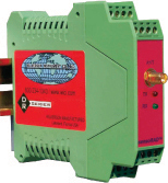
Polling Wireless Data Acquisition System DR9051R-01
Description:The DR9051R is an RF transmitter that will accept both analog and switch contact inputs. A 12 bit A/D converter is used to digitize the analog data. Analog data and switch status is then read when polled by the companion DR9050 Master Control Unit. The DR9050 MCU, under the control of a Modbus controller such as a PLC, polls the DR9051R and outputs the data in Modbus RTU format. A single DR9050 can poll up to 247 DR9051R’s utilizing a single Hop sequence. The switch inputs require a standard contact closure or an open collector NPN transistor. The DR9051R has a Repeater capability that allows it to pass data to and from an obstructed DR9051R. Two different RF modules, which operate on different frequencies, are available for the 900 MHz band. Each has 7 hop sequences. With this choice, a total of 14 hop sequences are available. The radio transmitter outputs 100mW (20 dBm) in the 902 to 928 MHz unlicensed ISM band. It uses frequency hopping, spread spectrum technology to allow multiple transmitters to work in the same locale without interference. A DIP Switch on the PC board is used to set the hopping sequence. With proper antenna and cable selection, the DR9051R can transmit up to 20 miles line of sight. The DR9051R provides isolation between analog inputs, output, and power source. The isolation makes the product useful for measuring input signals with high common mode voltages and for breaking ground connections to eliminate ground loops. Switch inputs pull a DC current through the LED of optoisolators. The excitation current is taken from the DC power source. The power source is isolated from the overall circuit by a transformer coupled power supply. Screw terminal blocks that plug into the case allow easy wiring and removal of products. All of the DR Series of products provide transient protection to help eliminate damage from lightning and from other transients created on the power and signal leads. Specifications:
NOTE: This unit must be used with a DR9050 Master Control Unit. |