Wireless Data Acquisition System sensoRAD™ DR9050
|
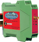
Wireless Data Acquisition System DR9050
Description: The DR9050 is the control unit of a wireless data acquisition system comprised of the DR9050 and the remote transmitter DR9051R. A Modbus controller, needing data from the remote locations, is required to manage the system. It may be any device that communicates with the Modbus RTU protocol using half duplex RS485 or RS422 communication wiring. From 1 to 247 DR9051R’s can measure analog signals and switch contacts and transmit the data, by radio, to the DR9050. The DR9050 is the access point to all of the DR9051R’s in the system. It appears transparent to the Modbus system which can take data from all of the DR9051R’s on the system by using the correct System address. The DR9050 can be wired, on the RS485/422 line, in parallel with other Modbus devices to form a system of wireless and hard wired devices. The DR9050 provides two outputs for the data. One is a standard Modbus RTU protocol and the other is an RS232 output that communicates with the Wilkerson Instrument Company software supplied with the System. An internal switch allows the selection. The Wilkerson Instrument Company software allows the programming of DR9051R addresses in the range 1 to 247 and also allows monitoring of data, RF signal strength, and other parameters of the wireless system. Each DR9051R has a factory address written into its program. The User must use the supplied software to assign a System address (1 to 247) to each of the Factory addresses. The System address assignments can be changed at the will of the User. The factory addresses are inviolate and are never duplicated in any other DR9051R. The Factory address is written on the circuit board of each DR9051R. It is also on the product’s label. Since the product enclosure can be easily removed, the circuit board should be referenced for accuracy. The RS232 port can also be used for custom software to generate a data acquisition system. Range between the DR9050 and the polled DR9051R’s can be in excess of 20 miles, depending on antennas used and the terrain between the antennas. A Wireless Signal Conditioning Engineering Manual is available by contacting sales@wici.com. This manual provides data and information on how to select antennas and calculate distance between communicating radios. Operation Logic The System is without activity until a Modbus controller or the User software makes a query for data. When the DR9050 receives a query, it cross references the System address to the Factory address and queries the DR9051R’s using the Factory address. The selected DR9051R processes the data on its inputs and responds to the DR9050. The DR9050 receives the data and sends the appropriate response to the source requesting the data. If the DR9050 is running in the RS485/422 Modbus RTU mode, the data reported is in the Modbus protocol. If the DR9050 is running in the RS232 mode, the DR9050 reports all available data from the DR9051R. This data includes:
DR9051R Description The DR9051R can monitor 1 or 2 analog signals, depending on type, and 4 switch contacts. Each time the unit is queried by the DR9050, it processes the analog and switch data and responds to the query with all analog and switch data and confirmation that the data is from the correct source. The DR9050 sorts the data and responds appropriately, based on the query source. The radio receiver in each DR9051R in the system receives every transmission made, but only responds when its unique address is received. Valid system addresses are from 1 to 247, in compliance with the Modbus standard, but factory installed addresses are used between the DR9050 and the DR9051R's. Radio Modules The radio transmitter and receiver in the DR9050 and DR9051R utilizes spread spectrum, frequency hopping technology to allow several systems to function in the same area without interference. The HOP number can be changed with the Wilkerson Instrument Company supplied software. Two radios are available for the 900 MHz band and each has 7 available Hop sequences. This provides the possibility of a total of 14 systems in the same general location. Both are license free in North America. A 2.4 GHz radio is available which has 7 Hop sequences. Antennas Generally, a polling system will have an omni directional antenna installed for the DR9050, since it must transmit and receive in many directions to communicate with each DR9051R in the system. Each DR9051R should have an antenna type dictated by signal strength requirements. Antennas are available in several forms, such as a low gain whip, high gain whip(omni), yagi, and parabolic reflector. See the Wireless Signal Conditioning Engineering Manual for detailed requirements of antenna systems. DR9051R / DR9050 User Software The User software contains 3 sections that are used to provide setup and operational functions for the system. They are: System Address Editor - Allows System addresses to be assigned to DR9051R units by Factory address. Allows comments to be saved with each address. Writes address data to the DR9050 EEPROM memory. All programming for the system is done at the DR9050. Saves address data in a text file for documentation purposes. Query Data Controller - Allows the interrogation of any DR9051R for data. Presents the data in binary form and analog data in User selectable Engineering Units. Lets the User automatically rapidly repeat a query to a single DR9051R so trends may be observed in real time. Since the data includes received signal strength for the DR9050 and DR9051R, this feature can aid in antenna installation and alignment. HOP Number Editor - If circumstances arise, such as a second system in the same general area, The HOP Number editor allows the User to do a broadcast command to all DR9051R units to change their HOP number to a new value. This editor also allows the DR9050 Hop number to be changed selectively, so it can change the HOP number of a single DR9051R. User Communications The DR9050 has an RS485/RS422 half duplex digital output with a Modbus RTU protocol. The terminal blocks for the RS485 connection has 3 sets of terminals internally tied in parallel. One set is for the cable input. Another set for a parallel cable to another device, and the remaining set for a termination resistor on the cable, if one is required due to cable length. Communications between the DR9050 and the PC with the User software is with a serial port. An adapter that fits the DR9050 plugs into the DB9 connector from the PC. The adapter end is a 4 pin terminal block that plugs into the DR9050. Specifications:
|
|||||||||||||||||||||||||