Wireless,Analog,Switch,Input,Output,Point To Point,Transceiver,sensoRAD,DR9031-01,Wilkerson Instrument

Wireless Analog & Switch Input/Output Point To Point Transceiver sensoRAD™ DR9031-01


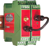
Wireless Analog & Switch Input/Output Point To Point Transceiver

DR9031-01Wireless,Analog,Switch,Input,Output,Point To Point,Transceiver,sensoRAD,DR9031-01,Wilkerson Instrument

Wireless,Analog,Switch,Input,Output,Point To Point,Transceiver,sensoRAD,DR9031-01,Wilkerson Instrument

Features:

  • Two DR9031 products make a bi-directional acquisition and control system
  • Send and Receive Data in Both Directions
  • Inputs Available For DC Voltage or DC Current, RTD, or Bridge
  • Dual DC Voltage or Current Inputs—Individually Isolated
  • Bridge Input Provides Precision 10VDC Excitation For 4 Bridges
  • Four Digital Inputs For Contact Closure or NPN Transistor Status
  • Dual 4-20mA outputs
  • Four Optically Isolated NPN Transistor Digital Outputs
  • Each DR9031 can have different analog inputs
  • Plug-In Terminals - DIN Rail Mount - Steel Clip
  • Line of Sight Range to 20 Miles With 915MHz Band Radio
  • Line of Sight Range to 10 Miles With 2.4GHz Band Radio
  • 915MHz ISM* Band - 2 Versions, 14 Hop Sequences
  • 2.4GHz ISM* Band - 1 Version, 7 Hop Sequences
  • Spread Spectrum, Frequency Hopping Technology*
  • 5 Year Warranty (1 Year on Radio Module)

Description:

The DR9031 is a 2-way wireless transceiver set which will send 1 or 2 analog channels and 4 digital switch status channels in both directions.

The transmitter input will accept both analog and switch contact inputs. The switch inputs require a standard contact closure or an open collector NPN transistor.

Dual channel DC voltage or current inputs are available. Each channel may be different.

Single channel RTD and Bridge inputs are available. The RTD input accepts 100 ohm platinum, 2 or 3 wire sensors. The Bridge input provides a precision 10VDC excitation supply that will drive four 330 ohm bridges in parallel to provide an average output from the 4 sensors.

The DR9031 provides isolation between analog inputs and power source. The DC Inputs are individually isolated. This isolation makes the product useful for measuring input signals with high common mode voltages and for breaking ground connections to eliminate ground loops.

RTD and Bridge sensors are inherently isolated, therefore the input circuits are only isolated from the power source.

A 12 bit A/D converter is used to digitize the analog data. Analog data and switch status is then transmitted to the companion DR9031 Receiver where the analog signal and switch status is reconstructed.

Dual channel input analog data is reconstructed as dual 4/20mA outputs. Single channel analog inputs are reconstructed as two 4/20mA outputs proportional to the input.

Switch status output is 4 optically isolated NPN transistors.

Three radio modules are available for the DR9031, two 915MHz band versions with 7 Hop sequences each and a 2.4GHz band version with 7 Hop sequences. They use spread spectrum, frequency hopping* technology. These choices provide 21 different Hop sequences that allow 21 systems to work in the same locale without interfering with each other.

A DIP Switch on the Transmitter PC board is used to set the Hop sequence.

With proper antenna and cable selection and a 915MHz band version radio, the DR9031 can transmit up to 20 miles. The 2.4GHz band version can transmit up to 10 miles.

Screw terminal blocks that plug into the case allow easy wiring and removal of products.

All of the DR Series of products provide transient protection to help eliminate damage from lightning and from other transients created on the power and signal leads.

Specifications:

INPUT

Dual DC Voltage or Current

Current

  • Min Span = 1mA
  • Max Span = 50 mA

Voltage

  • Min Span = 100 mV
  • Max Span = 150 V

Accuracy

  • ±0.1% of span

Linearity

  • ±0.05% of span

Strain Gauge

Span

  • 0.5 mV/V to 1000 mV/V

Accuracy

  • ±0.1% of Span

Linearity

  • ±0.01% of Span

Excitation

  • 10 VDC Precision Supply for up to 4 Strain Gauges 125 mA Maximum

RTD

  • 100 ° Platinum, 2 or 3 Wire .00385 or .00392 Alpha

Range

  • -200 to +850°C Maximum 15°C Span Minimum

Accuracy

  • ±0.05% of Span

Linearity

  • ±0.05% of Span

Open Sensor

  • Full Scale

COMMON MODE REJECTION

  • 100 dB, DC to 60 Hz

Switch Input

Open Circuit Voltage

Equals Power Input

  • 12 to 24 VDC

Closed Circuit Current

  • 4 to 8 mADual DC

OPERATING TEMPERATURE

  • -13°F to 167°F/-25°C to 75°C

TEMPERATURE STABILITY

  • ±(0.01% of span)/°C max

Output

Analog

  • Dual 4/20 mADC
  • 12 VDC Compliance

Digital Four Optically Isolated

Open Collector NPN Transistors

30 VDC Max Voltage,

30 mA Max Current Operates in Saturated Mode

RADIO

Frequency

  • 915 Band
  • 908 or 922 MHz
  • 2.4 GHz Band (2.4000 - 2.4835 GHz)

Spread Spectrum Type

  • Frequency Hopping, Direct FM

I/O Data Rate Tx to Rx:

  • 9600 bps

Update Rate

  • Approximately 8/S

Range (Line of Sight)

  • 915 MHz Band -- Up to 20 Mi.
  • 2.4 GHz -- Up to 10 Mi.

Receiver Sensitivity:

915 MHz Band

  • -110 dBm @ 9600 baud

2.4 GHz Band

  • -105 dBm @ 9600 baud

Transmitter Power:

915 MHz Band

  • 100 mW (20 dBm)

2.4 GHz Band

  • 50 mW (17dBm)

Connector:

  • Reverse Polarity SMA Female

Certification:

  • FCC Part 15.247

OPERATING TEMPERATURE

  • -15°F to 160°F
  • -25°C to 70°C

POWER

  • 12 or 24 VDC
  • 1.5 Watts Max